Sony WH-1000XM6 FCC Teardown (Update)
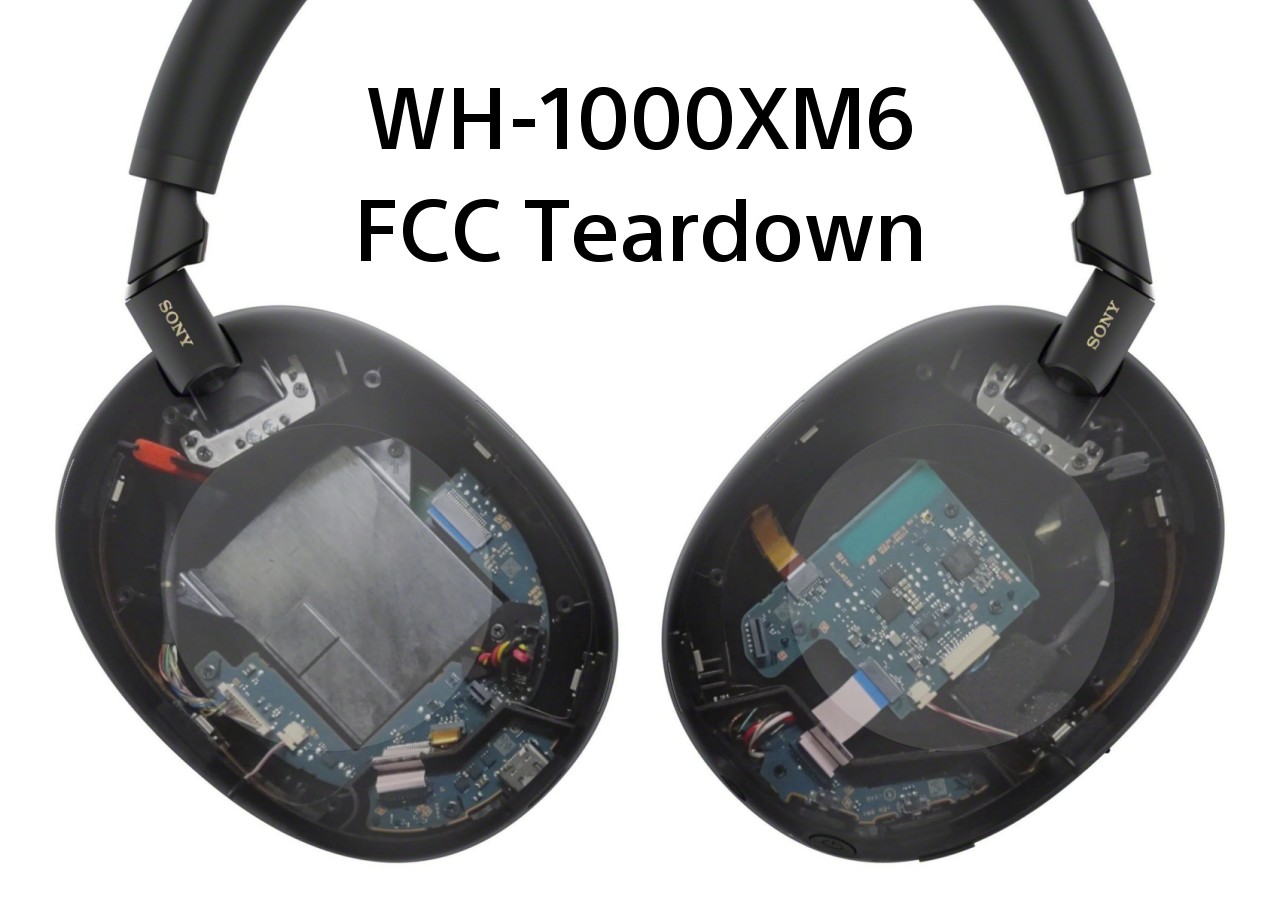
My WH-1000XM6 specification deep dive has been posted, so now let us look at the inside, and see what has changed. The FCC photos reveal a lot of details, and while we lack a 52Audio teardown, iFixit have uploaded their own teardown on YouTube, with a lot of details. Do make sure to check it out. Okay buckle in, this will be a long post. Update: 52Audio has posted their teardown.
Sony WH-1000XM6 Amazon US | Sony WH-1000XM6 Amazon Germany
Starting with the earpads, the FCC filing does not have any photos of the back, but thanks to MrWalkman, we have a photo. Five clips secure the pads, and 2 pins are used to position them correctly.
 |
| Sony WH-1000XM6 earpads - backside |
 |
| The ribbon cables going from the driver are held in place with a small little piece (red arrow), which needs to be removed first before the driver assembly can be removed. |
With the earpads removed, we can see the drivers, and the wear detection sensor on the left side surrounding the driver. The design here is similar to the WH-1000XM5, but there are some differences like no foam covering the driver, and what I would call, simpler surfacing on the plastic. I wonder if a 40mm driver would have fit. Sony went back to a folding hinge, perhaps they should have gone back to a 40mm driver as well, considering this is a flagship model. Thoughts?
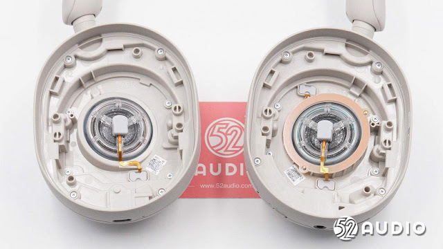
Here is the WH-1000XM5 for comparison (ignore the arrows).
And with the foam inserts removed, the surface of the WH-1000XM5 plastic seems more complex, with a lot more lines, angles, and random spaces. Also a lot more room for dirt and grime.
 |
| Right side (L), Left side (R) |
The WH-1000XM5 pads will not fit on the WH-1000XM6, as the pins and tabs are different.
The driver assembly is held on with 5 small screws on both sides. This provides very quick and simple access for repair and replacement of parts. Whether owners will be able to readily purchase parts in their region remains to be seen.
With both right and left driver assemblies removed, we can see inside the earcups.
 |
| Click to zoom in |
The WH-1000XM6 adopts a different construction to the WH-1000XM5. One no longer needs to remove the earcup side to access the PCB. Sony has instead used a design similar to its lower end models like the WH-CH720N or WH-CH520, where after removing the driver, there is access to all the components. This is a good change as it makes repair much easier and simpler. The hinge mechanism has also been significantly changed. The design is more compact and appears to use actual metal in its construction. The XM5 hinge took up a good portion of the interior of the earcup and looked to be made all from plastic. More on the hinge later.
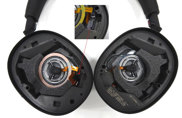
Another change is Sony switching the driver connection from soldered to a dedicated connector. With this change, all connections are now using a connector which can be easily disconnected. As no connections require desoldering, repairs will be much simpler and faster.
 |
| Sony WH-1000XM6 driver connectors - closeup |
Starting with the right side, we have the battery compartment, the SUB board, and the USB board. The top of the earcup is the new hinge, which I will look at next in more detail.
 |
| Sony WH-1000XM6 right earcup |
New Hinge
When I refer to the hinge, I mean the parts inside the earcup, and not the folding section on the headband. I am sure that can be taken apart, but we have no photos of this (actaully we have iFixit x-ray). The XM6 internal hinge is very different to the XM5. For instance, it takes up much less room and uses a lot more metal in its build. The design is a lot simpler and much more repairable, as seen in the screenshots below from the iFixit teardown video.
 |
| Source: iFixit teardown video |
The main metal bracket is held on with 4 screws, 2 on the side, and 2 in the middle. The 2 middle screws attach the headband bracket to the earcups.
 |
| Source: iFixit teardown video |
 |
| Source: iFixit teardown video |
Removing the main bracket, we can see the headband bracket slotted into place, and aligned with 2 plastic pins. The headband can then be removed from the earcup, see the video for the procedure.
 |
| Source: iFixit teardown video |
Here is the headband bracket. While it is not shown in the video, I suspect the metal bracket is connected to the metal in the folding hinge, but we will not know for certain until someone takes it fully apart. Edit, we have the iFixit x-ray which shows inside the plastic, thank you anonymous comment. It appears the headband bracket is NOT connected to the hinge. Here are the screenshots from the iFixit video.

I suspect this support piece looks like similar to the seen in the ULT wear, meaning the insert is metallic, but piece it fits into, is all plastic. Until we get a complete hinge teardown, we have no way to know how it is constructed.
 |
| ULT wear hinge - Source: Reddit |
Another angle of the hinge.
 |
| Source: AV-Watch |
No screw is visible in this photo from AV-Watch. I think this screw could be in the same spot as the plastic piece that is at the end of the headband cushion. How one gets to this screw is a mystery. Perhaps this plastic piece comes off?
The back of this top metal piece can be seen in these 2 photos below.
Sony could release a teardown video of the hinge on their YouTube channel, demonstrating the strength and build quality of the hinge to ease people's minds, but not going to happen. So while we have no photos of any broken WH-1000XM6 hinges, there is always a chance that lower support piece could break, if the plastic suffers from the same issues as the WH-1000XM5 plastic.
Now back to the inside of the right earcup.
The battery compartment is held on with 2 screws near the top, removing these and unplugging the connection is all that is required to remove the battery.
 |
| Source: iFixit teardown video |
Removing the XM6 battery is much simpler when compared to the XM5, which required the removal of the exterior earcup piece as well. The XM5 battery was also taped into place, but the iFixit video does not mention if the XM6 battery is taped in place as well. Unless they did, then I missed that. The battery compartment is made from 2 pieces, removing the top cover reveals the actual battery.
 |
| Source: iFixit teardown video |
- WH-1000XM6 battery - 1050 mAh 3.8V (3.99 Wh)
- WH-1000XM5 battery - 1200 mAh 3.8V (4.56 Wh)
The drop from 1200 mAh to 1050 mAh is a decrease of 12.5%, which is substantial, yet the WH-1000XM6 offers the same battery life as the previous model. This is quite impressive. If Sony kept the 1200 mAh battery, SBC/AAC/LC3 battery life with NC on, would be up to 34 hours, and LDAC with NC on up to 29 hours. This is just my calculated estimate, so I could be wrong.
The battery connector appears to be identical on both models.
 |
| Source: iFixit teardown video & 52Audio |
- VDL - model 643741PF3
- Springpower - model 633741
The WH-1000XM5 battery model is 723741. From my understanding, the numbers represent the dimensions. So the WH-1000XM6 battery is around 41mm x 37mm, with a thickness of 6.3-6.4mm. While the WH-1000XM5 battery would fit in the battery compartment, the thickness might not permit the battery cover to close. If I had the money to burn, I would try and transfer over the XM5 battery to see if it would fit.
Here is the SUB_A PCB. The quality is not that great, but it will do for now. I have labelled the various connections.
- Ribbon cable connector for the touch pad
- Battery connection
- Feedback microphone array flex PCB connection
- Feedforward/Voice microphone array flex PCB connection
- USB board connection
- Driver connection
- Connection for cable bundle to left side
This is pretty much the same on the WH-1000XM5, but the components are arranged differently. Not sure why the battery connection on the XM6 has the additional plastic piece, but I am sure there is some good reason.
 |
| source: 52Audio |
Flipping the board over, we just see components and chips, with no connections.
We cannot ID any chips with certainty, but I suspect the top right corner chip is an Atmel microcontroller. The bottom left angled chip is most likely a charging IC from MPS Core Source. This is based off what the XM5 has, which has very similar components.
 |
| Sony WH-1000XM5 Sub PCB - source: 52Audio |
Moving the the smaller USB port board.
- SUB-A board connection
- LED indicator
- Resettable fuse
The WH-1000XM5 also has a resettable fuse, which can be seen below to the right of the USB port.
 |
| Sony WH-1000XM5 USB PCB - source: 52Audio |
Finally we have the touch pad underneath the battery compartment. The WH-1000XM5 used a flex PCB for its touch pad, but Sony went back to regular PCB on the XM6, like in the WH-1000XM4. Why this change, I have no idea. Maybe less false inputs?
Moving to the left side, we have the main PCB, and the 3.5mm jack board. The main PCB is held on with 3 screws, and the jack board with 1. Very easy to repair if anything needs replacing.
The main PCB shape has changed slightly when compared to the XM5, but we have no information if the size has changed. Sony claims they have "optimised components and circuitry to minimise interference, and shorten travel of the signal" on the new PCB, especially around the QN3. I am sure this is true, but I would not know even how to check this.
For those wondering where the QN3 is, it is the chip in the square chip in the middle on the left side (I have it labelled below). Unfortunately it is impossible to visually identify any chips through text, but the iFixit teardown does have a photo of the main PCB, so we can use that to ID some of the components.
 |
| Source: iFixit teardown video |
- Mediatek MT2833A - Sony V2
- already confirmed by FCC manual
- GD25LQ64EN - NOR Flash 64 Mbit
- Sony QN3
- LATTICE ice40ul1k (for LED indicator)
- See details in corner of photo
- Feedforward/Voice microphone array flex PCB connection
- Feedback microphone array flex PCB connection
- 3.5mm jack PCB connection
- Driver connection
- Right side cable connection
The iFixit teardown lacks a view of the reverse side of the PCB, so we are stuck with the FCC filing photo, which is does not have the best quality.
We have a few chips on the reverse side. Could the top chip be another flash memory chip? The size and shape match the one from the WH-1000XM5, but why have another chip on this side, when we already have on the other? No idea. We have 2 more mystery chips under the top one, no idea what these could be. Some chips used in the WH-1000XM5 are absent here, like the Cirrus Logic CS47L63 (high-performance, low-power audio DSP), and a gyroscope IC, perhaps one of the unknown chips.
In the lower end of the left earcup is the jack PCB, with the 3.5mm port, the LED indicator light. and the 2 button controls. The board is connected to the main PCB through a ribbon cable, so like all other parts, can be easily replaced.
Finally let us look at the noise cancellation microphones. There are 12 in total. First up, the feedforward/voice microphone array.
 |
| Feedforward/voice microphones - left side (top), right side (bottom) |
The FF/voice MEMS microphones are all on a ribbon cable, like in the XM5. The XM5 has 4 microphones on the left side, and 3 microphones on the right, in its arrays. I compared the size of the microphones using the rulers in the photos, and the MEMS mics are the same size.
The feedback microphones now come in pairs.
 |
| Left side (L), right side (R) |
The left side has the wear detection sensor, which is why the ribbon cable is wider. From my understanding, one mic faces towards the the ear, the other towards the driver. I am still not sure 2 feedback microphones are necessary, but I suspect Sony has compared the performance of 1 vs 2 mics, and deemed that 2 is better than 1.
Wind Noise ReductionSony claims they have redesigned the structure around the microphones and refined their placement to reduce the effects of wind noise. So can we see this? Here is the mic structure from the WH-1000XM5.
 |
| source: 52Audio |
And here is the WH-1000XM6 microphone structure courtesy of the iFixit video. In the video, there are more angles of the mics, but these 2 below are the best I could find.
The structure seems a bit different, but it is difficult to say for certain how much different. The mics do appear to be placed few millimetres deeper in the new model. Maybe once we get a 52Audio teardown, they will have better photos of the XM6 mic structure up close, allowing us to get a better comparison.
QN3
Finally turning back to the QN3. The iFixit photo lacks the details to give an easy ID, but I may have figured out what is written on the chip. With some photo enhancement magic, this is the result. You may have to zoom in to see the it more clearly.
I believe the text is D3785. There is no SONY logo on the chip like the QN1 (seen below on the right).
The first 3 numbers were easy to identify, 378, but the last one was a challenge, either it was a 5 or a 2. Looking at other Sony chips, it was obvious the number looked closer to a 5 (red arrow), than a 2 (blue arrow). If D3785 is the actual text on the chip, then I am confident we are looking at the CXD3785, which is part of Sony's Audio IC line. Unfortunately the chip is absent from the list on the page.
Update: With 52Audio's teardown, we can see D3785 was the correct text on the chip.
We have a bit information from Sunnic, such as the CXD3784, which is absent from Sony's Audio IC page. Lucky for us, Sunnic has a news post with a roadmap from 2021. I have no idea how I missed this before.
 |
| Sony Audio IC roadmap |
- CXD378x over-ear and in-ear headphones
- CXD378x TWS
- CXD379x TWS
- CXD329x TWS
I suspect the QN3 in the WH-1000XM6 is this new CXD378x for OH/IE headphones, that went into production in 2023. This appears to be the successor of the CXD3782. This chip is a Hybrid noise cancelling (feedforward/feedback), with an integrated 6-band EQ, 6-channel ADC, and 2-channel DAC. The datasheet can be found here. The block diagram only shows single noise cancelling, which contradicts the description, so maybe the block diagram is wrong.
I suspect the QN3 (CXD3785) adds more ADC channels, and a 10-band EQ. Anything additional will remain a mystery. Unless Sony decides to sell this to other customers, we probably will not see a datasheet online. Finally, withe the roadmap information, I have a hunch that the QN2e could be the CXD379x or CXD329x, as the QN1e was the CXD3781. But that is a post for another day.
And that concludes the this teardown post, make sure to check out the iFixit teardown, as it provides additional details not posted here.
Sony WH-1000XM6 Amazon US | Sony WH-1000XM6 Amazon Germany
Sony WH-1000XM6 Amazon Canada Pre-order
If you wish to support my work here on the blog, you can do so through Buy me a coffee, Click the banner for more details. Thank you.


At the beginning of the video, an X-ray of the headphones is shown. It looks like there will be the same problems as version 5 - the hinge is also attached metal/plastic
ReplyDeleteyou're right, will update the post with info. unfortunate discovery.
DeleteWell, not necessarily. I had my XM5 for over 2 years without issues, and the hinge on the XM6 seems like an improvement.
Deletemy xm5 also has no issues with the hinge (knock on wood), but I baby mine, as I do with all of my tech.
Delete