Sony WF-1000XM5 Teardown by 52Audio
We had to wait a while before 52Audio performed a teardown of the WH-1000XM5, but thankfully we did not have to wait that long with the new WF-1000XM5. I already did a preliminary teardown analysis in my original WF-1000XM5 article, and in my Sony V2 processor comparison, but with this new teardown, we can see a lot more and in better detail.
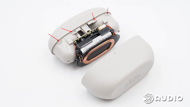
Starting off with the case, the bottom section is held on with tabs that surround the perimeter of the case (see red arrows). There are 4 tabs in the front and 2 in the back.
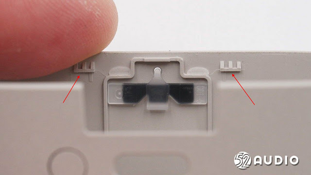
Here is a close up of the tabs inside the case. I believe the best way to remove the bottom half is to use a plastic spudger and go into the seam and work your way around the case to pop the tabs out of their spots.
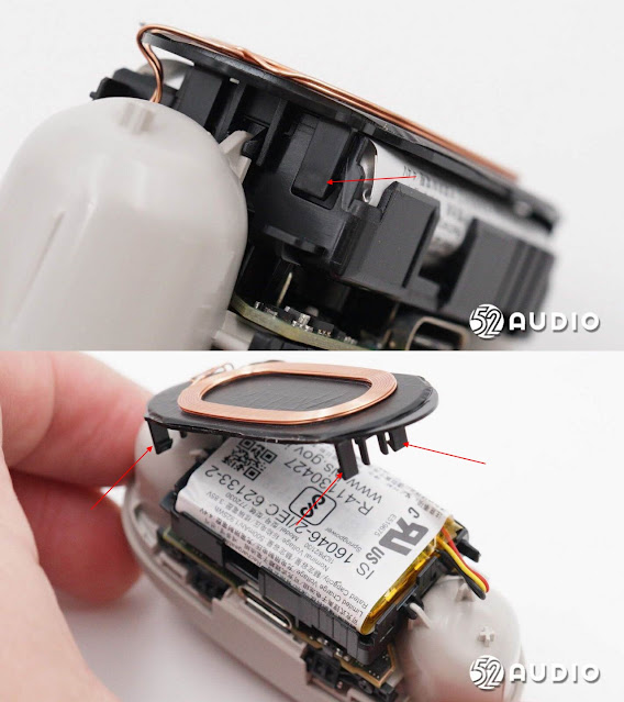
The wireless charging coil on the bottom is held on with clips (4x) as well. This will have to be removed before the battery can be accessed.
The battery fits inside a small enclosure which means a larger battery cannot be fitted into the case.
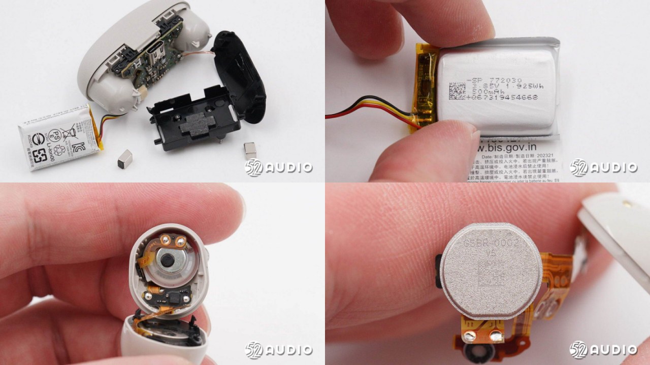
Removing the battery, we can see the capacity information. The battery is connected to the charging case PCB with a connector, like in the WF-1000XM4. This means it can be easily swapped if a proper replacement can be found. I do not recall if any other Sony products use this size of battery. I would have to check the other teardowns.
We are looking at a 3.85V 500 mAh Li-ion battery. The WF-1000XM4 for comparison has a 3.85V 520 mAh battery. So even though the WF-1000XM5 has a smaller battery capacity, it provides the same extra 16 hours from the case like the WF-1000XM4. This is probably achieved through the use of newer more energy efficient components in the earbuds.
The battery has a protection board beside it, removing the foil reveals "a lithium battery protection IC and MOS tube, as well as a thermistor to detect the battery temperature" according to 52Audio. But which is which, I have no idea.
Next up, we can look at the charging case PCB.
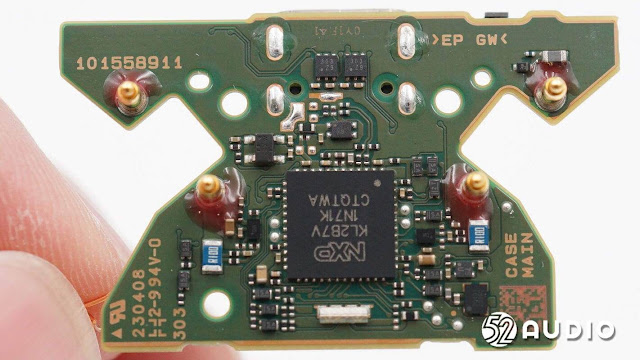
One side has the main microcontroller from NXP, the K32 L2B series. This is an upgrade over the chip found in the WF-1000XM4 which was part of the same series but only came with 64KB of flash memory, versus the 128KB of flash memory in the WF-1000XM5. Whether there are other differences like frequency is unknown.
In the bottom of the photo we can see the case notification LED, with the charging pins at the top of the board.
Flipping to the other side, we have the USB type-C port, the battery connection, the wireless charging coil connection and the pairing button beside the USB port.
52Audio has a few of the chips identified. First up is the Analog Devices MAX77857.
The MAX77857 is a is a high-efficiency, high-performance buck-boost converter suitable for systems requiring a wide input voltage range (2.5V to 16V).
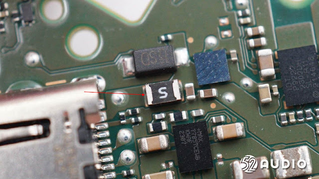
Beside this chip, we have something we first saw in the WH-1000XM5 teardown, a resettable fuse for the Type-C port. Naturally going back to the WF-1000XM4, I would a similar fuse similar fuse, so this is not a new addition.
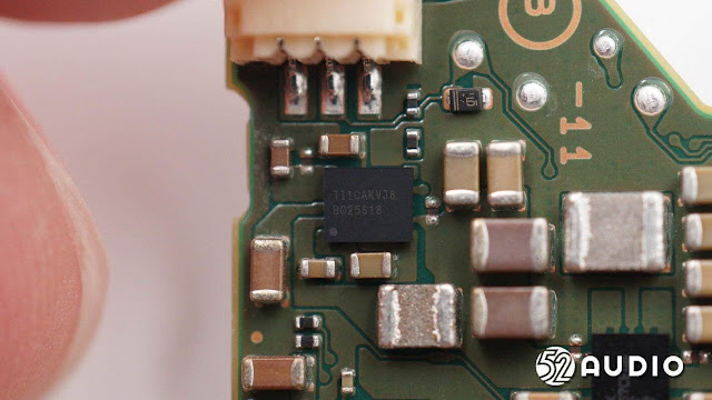
Next up is a chip from Texas Instruments, the BQ25618. The same chip was used in the WF-1000XM4.
This chip is a charging IC which integrates switching charging, synchronous boost converter and voltage protection functions. It supports 22V withstand voltage and can reduce battery leakage to 6uA in transport mode. It is used to charge the built-in lithium battery and charge the earbuds.
Finally we have the Renesas P9222. This IC is "an integrated single-chip wireless power receiver IC (Rx) for up to 5W applications. The P9222-R is highly efficient at light loads and very well-suited for low-power applications such as earbuds case charging."
Turning to the earbuds now.
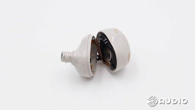
Unfortunately the 52Audio article does not mention if there is any adhesive in the joint, so perhaps it is a friction fit? But I suspect there is some kind of seal, which is rather difficult to see in these photos. A plastic spudger would be the best tool to open the earbuds. But be careful when separating the 2 halves, as there is a thin ribbon cable running between the 2 pieces, which could be damaged if you pull the 2 pieces apart.
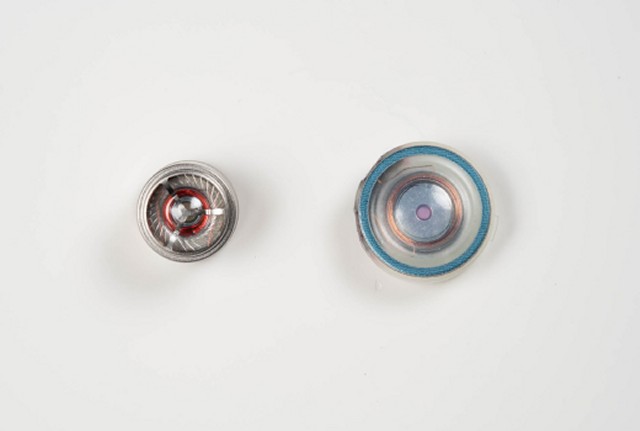
We can see this ribbon cable here (#2), The new driver is soldered to the main ribbon cable assembly (#1). The new driver takes up a lot of the interior space unlike in the WF-1000XM4 which was a much smaller. Below is a size comparison of the new driver (R) and the old driver (L).
 |
| Photo: Sony |
The entire interior structure can be fully taken out of exterior shell.
I do not see anything which affixes the assembly in the shell, but it might also be a friction fit here as well. Difficult to tell with the photos 52Audio has provided.
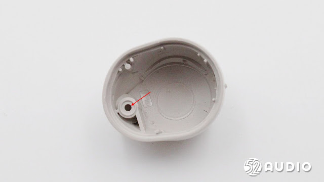
In this photo, we can see the hole for the the MEMS microphone which is used for voice pickup and for the feed-forward NC functionality. Not sure why Sony decided to combine both these functions into one microphone. In the WF-1000XM4, there were 2 mics, one for NC and one for voice. I suspect the NC mic would still cancel noise when on a voice call. The combined NC/voice mic is also present in the LinkBuds S, so perhaps if the design worked for Sony there, this is why it was copied for the WF-1000XM5.
On the opposite side of the earbuds is the pressure relief hole, which is covered by a waterproof but breathable membrane. In the WF-1000XM4, this relief hole was on the underside near the driver and proximity sensor.
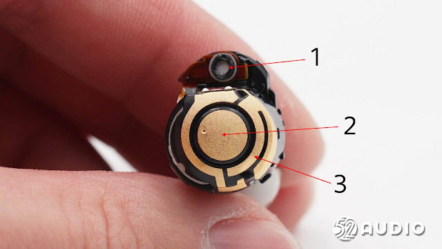
The top of the earbuds has the pierce which contains the touch sensor (#2) and built in wireless antenna (#3). The feed-forward NC mic (#1) is covered by a similar mesh found near the pressure relief hole.
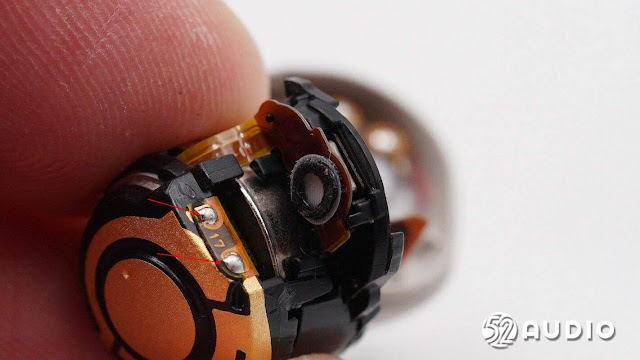
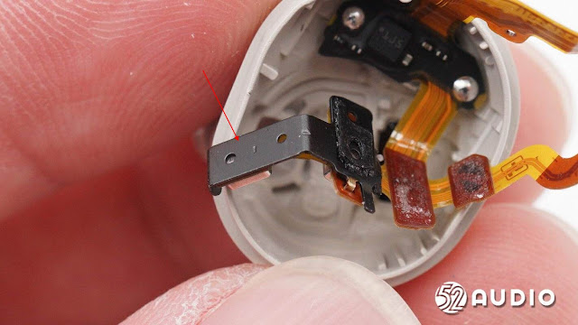
In this side photo, we have the positive (upper) and negative (lower) battery contacts, with the SiP (#2) positioned under the touch sensor/antenna. The design is very compact with little wasted space.
Here we have another close up shot of the mesh of the feed-forward NC mic. The arrows on the left highlight the solder joints which connect a ribbon connector from the SiP to the touch sensor/antenna assembly.
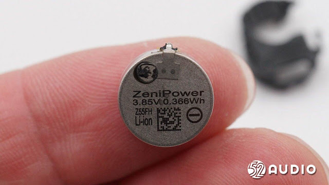
Thanks to the INZONE buds FCC teardown, we already knew of existence of the Z55FH battery from Zenipower. And thanks to the INZONE buds engineer interview, we knew that battery powers both the INZONE buds and the WF-1000XM5. And now with the 52Audio teardown we have physical confirmation of the battery in the WF-1000XM5. As for the size of the battery, from a battery certification document from China, the diameter is 12.1mm but I do not have any height information.
If the Z55FH turns out to have the same height as the Z55H, then one could swap this new battery into the WF-1000XM4 to achieve a better battery life. Question now is, will the Z55FH become available for purchase?
Turning back to the WF-1000XM5, with the Zenipower battery fiasco in the WF-1000XM4, would the presence of a new Zenipower battery in the new WF-1000XM5 make you hesitant from it? Leave your thoughts in the comments.
The new battery is held in place with a plastic piece, with the battery held on with adhesive on the bottom of the plastic. A small magnet on the right side helps line up the earbuds with the magnets inside the case.
52Audio does not identify this chip (11 30206 IC) in their write up, but I am going to guess this is the the battery protection chip. A similar chip in size and colour is found in the WF-1000XM4 and this was identified as the battery protection chip.
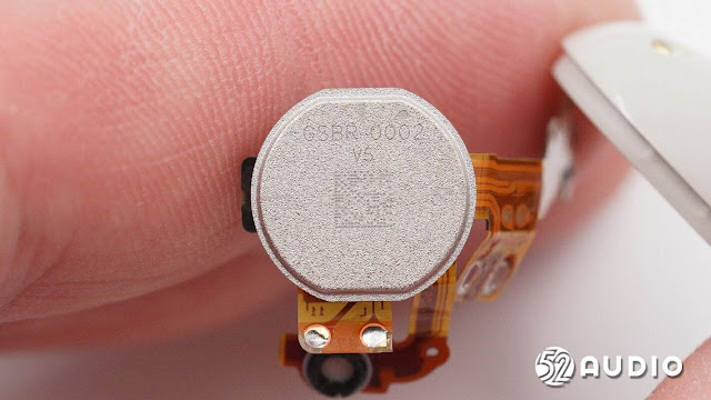
Both of main chips, the V2 and the QN2e are covered by a metal cover which is meant to reduce outside interference. In my Sony V2 article, I posted a photo of the GSBR-0002 from the FCC filing with version 4-3, and now we can see the production model is on version 5. Googling GSBR-0002 does not yield any results other than my blog and Goertek also changed their website, meaning they removed any information about the GSSBR-0001which was there initially.
Unfortunately 52Audio did not delid the SiP, so we cannot see the V2 and QN2e chips in their teardown.
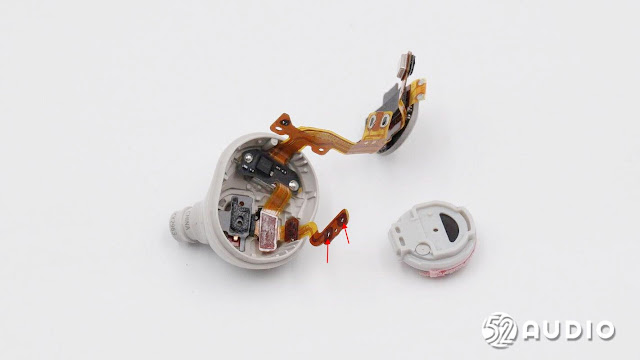
In order to detach the driver, one will need to de-solder the connections indicated by the red arrows.
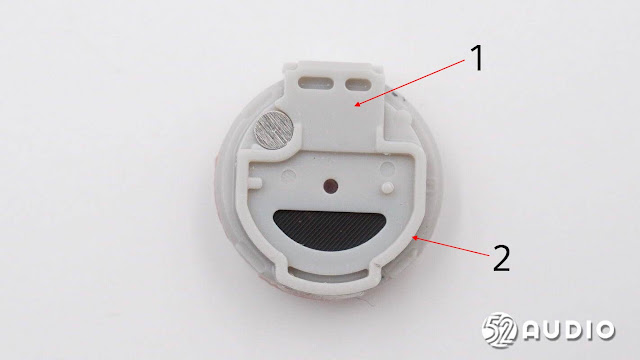
In the WF-1000XM5 post, I was wondering what the piece covering the outlet of the earbuds was, but it seems this is part of the driver unit in this teardown.. We can see the black mesh near the bottom, which covers the outlet of the earbuds. I do wonder if a flat plastic piece would damper the sound output from the driver? Anyone have any insight into this?
The piece covering driver (#1), has a rubber seal (#2) around the outlet that leads to the earbud tip. A similar seal was present in the WF-1000XM4 but it was not attached to the plastic. In the 52Audio teardown, we only have photos of the rear of the driver, so scroll back up to the WF-1000XM4/WF-1000XM5 driver comparison to see the front of the new driver.
With the driver removed, we can take out the 2 internal Feedback NC mics out. They are both on a metal (?) support.
Flipping this support over reveals the MEMS microphones.
We can see the 2 Feedback MEMS mics (#1), along with the proximity sensor (#2). The bottom of the support is visible in the outlet tip. My question is, would the extra NC mic have been better as a feedforward one rather than feedback? The WH-1000XM5 only uses 1 feedback NC mic, but has 3 feedforward mics. Sony could have perhaps used 2 mics for feedback NC and 2 mics for feedforward NC, with one mic performing voice pickup as well.
Naturally the extra mic along with additional processing would use up more battery, so this might be why Sony only used 3 mics in total, rather than 4.
I am sure someone will eventually have 4 mics on a set of wireless earbuds, and once that happens, it will become the norm.
Amazon US | Amazon Canada | Amazon UK | Amazon Germany
And now for some ranting.
Something that has been bugging me; it seems that Sony could have used a combination of a dynamic driver and perhaps 1 or 2 balanced armature drivers, there is space inside. Sony could have made the WF-1000XM5 slightly bigger to fit these parts in, they would still be smaller than the WF-1000XM4. Maybe this is just my flawed thinking that a mix of a dynamic driver and balanced armature drivers is better than just the one larger dynamic driver. But my XBA-A3s are my go to wired in-ear headphones almost all the time.
The counter argument can be made that with Bluetooth, the sound quality is not really there to warrant better sound quality from the earbuds. Yes we have LDAC, but even that is still lossy. Qualcomm does have their micropower WiFi coming soon, so if Sony used this or something similar in a future set of earbuds, true lossless sound could be delivered to the earbuds. With true lossless sound, the wireless earbuds would require better sound quality and perhaps a mix of dynamic and balanced armature drivers would be the ideal setup.
Photo Source: 52Audio WF-1000XM5 teardown















New firmware 3.0.1 is out. The XM5 earbuds finally support LE Audio with the Xperia 1/5 V smartphones.
ReplyDeletehttps://www.sony.co.uk/electronics/support/wireless-headphones-bluetooth-headphones/wf-1000xm5/software/00296559
Adds Quick Access support for Amazon Music
Note: Depending on your country or region, this benefit may not be available.
Adds support for the use of the LE Audio feature with Xperia 1 V and Xperia 5 V smartphones
Improves overall functionality
WH-1000XM4 are also updated (to 2.1.0)
E_D___B_A_N_G_E_R
WH-1000XM4 are on 2.5.0 though? I think you meant WH-1000XM5.
Deletehttps://www.sony.co.uk/electronics/support/wireless-headphones-bluetooth-headphones/wh-1000xm4/software/00261611
He definitely meant the XM4, which hasn't receive an update since May 2021.
DeleteWF-1000XM5, WH-1000XM5, LinkBuds and LinkBuds S just got new firmware update with support of Amazon Music in Quick Access. LinkBuds / LinkBuds S also got volume control with repeat tap and head tracking.
ReplyDeleteIs replacing the battery possible? Just need to solder a new one? A article on ifixit mentions it is welded making it harder, this teardown makes it seem simple.
ReplyDeleteYou can definitely replace Batteries🔋 of WF-1000XM5 Earbuds into wf-1000xm4 Earbuds (not the charging base) without any issues. Unless if you don't have Parkinson aka Shaky hands 👐
ReplyDeleteHi. I took the charging case apart to replace the battery but could not figure out how to place the two magnets under the board so the earbuds would attach magnetically. Any help would be greatly appreciated!
ReplyDeleteare the magnets not glued in?
DeleteI used hot glue becuase from the factory they use a very thin double sided tape that is weak and gives out
DeleteNo, their not glued in. Just put the ear buds back during assembly and the magnets will snap snuggly into position.
DeleteI need help finding the capacitors on the case board, the dimensions seem to be 2.65mm x 2.15mm (LxW) which seems to be impossible to find, can anyone help?
ReplyDeletedigikey maybe?
DeleteBe careful when opening. I managed to damage the pairing button.
ReplyDelete